一、什么样的n阶矩阵才能对角化?
先说结论
定理1:
设 是方阵的m个特征值,依次是与之对应的特征向量,如果各不相等,则线性无关。
继续阅读“矩阵对角化”
xuenhua’s 站点

一元n次方程 的根为,其中。 那么(1)式可以写成下面的形式:
将其展开,并观察多项式系数,的系数: 常数项:
比较常数项和的系数,可以得到:
这就是一元n次方程的韦达公式。
神经网络是一组受人类大脑功能启发的算法。一般来说,当你睁开眼睛时,你看到的东西叫做数据,再由你大脑中的 Nuerons(数据处理的细胞)处理,并识别出你周围的东西,这也是神经网络的工作原理。神经网络有时被称为人工神经网络(Artificial Neural Network,ANN),它们不像你大脑中的神经元那样是自然的,而是人工模拟神经网络的性质和功能。
继续阅读“神经网络原理”反向传播(英语:Backpropagation,缩写为BP)是“误差反向传播”的简称,是一种与最优化方法(如梯度下降法)结合使用的,用来训练人工神经网络的常见方法。该方法对网络中所有权重计算损失函数的梯度。这个梯度会反馈给最优化方法,用来更新权值以最小化损失函数。 在神经网络上执行梯度下降法的主要算法。该算法会先按前向传播方式计算(并缓存)每个节点的输出值,然后再按反向传播遍历图的方式计算损失函数值相对于每个参数的偏导数。
我们将以全连接层,激活函数采用 Sigmoid 函数,误差函数为 Softmax+MSE 损失函数的神经网络为例,推导其梯度传播方式。
GDI+ 提供用于存储和操作图像的 Image 和 Bitmap 类。 Image 和 Bitmap 对象用一个 32 位数字存储每个像素的颜色:红、绿、蓝和 Alpha 各 8 位。 这四个分量的值都是 0 到 255,其中 0 表示没有亮度,255 表示最大亮度。 alpha 分量指定颜色的透明度:0 表示完全透明,255 表示完全不透明。
颜色矢量采用 4 元组形式(红色、绿色、蓝色、alpha)。 例如,颜色矢量 (0, 255, 0, 255) 表示一种没有红色和蓝色但绿色达到最大亮度的不透明颜色。
表示颜色的另一种惯例是用数字 1 表示亮度达到最大。 通过使用这种约定,上一段中描述的颜色将可以由矢量 (0, 1, 0, 1) 表示。 在执行颜色变换时,GDI+ 遵循使用 1 为最大亮度的惯例。
可通过用 4×4 矩阵乘以这些颜色矢量将线性变换(旋转和缩放等)应用到颜色矢量中。 但是,您不能使用 4×4 矩阵进行平移(非线性)。 如果在每个颜色矢量中再添加一个虚拟的第 5 坐标(例如,数字 1),则可使用 5×5 矩阵应用任何组合形式的线性变换和平移。 由线性变换组成的后跟平移的变换称为仿射变换。
例如,假设您希望从颜色 (0.2, 0.0, 0.4, 1.0) 开始并应用下面的变换:
下面的矩阵乘法将按照列出的顺序进行这对变换。
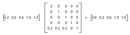
颜色矩阵的元素按照先行后列(从 0 开始)的顺序进行索引。 例如,矩阵 M 的第五行第三列由 M[4][2] 表示。
5×5 单位矩阵(在下面的插图中显示)在对角线上为 1,在其他任何地方为 0。 如果用单位矩阵乘以颜色矢量,则颜色矢量不会发生改变。 形成颜色变换矩阵的一种简便方法是从单位矩阵开始,然后进行较小的改动以产生所需的变换。
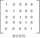
有关矩阵和变换的更详细的讨论,请参见坐标系统和变形。
示例
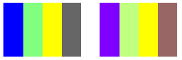
下面的示例采用一个使用一种颜色 (0.2, 0.0, 0.4, 1.0) 的图像,并应用上一段中描述的变换。
下面的插图在左侧显示原来的图像,在右侧显示变换后的图像。

下面示例中的代码使用以下步骤进行重新着色:
C#
Image image = new Bitmap(“InputColor.bmp”);
ImageAttributes imageAttributes = new ImageAttributes();
int width = image.Width;
int height = image.Height;
float[][] colorMatrixElements = {
new float[] {2, 0, 0, 0, 0}, // red scaling factor of 2
new float[] {0, 1, 0, 0, 0}, // green scaling factor of 1
new float[] {0, 0, 1, 0, 0}, // blue scaling factor of 1
new float[] {0, 0, 0, 1, 0}, // alpha scaling factor of 1
new float[] {.2f, .2f, .2f, 0, 1}}; // three translations of 0.2
ColorMatrix colorMatrix = new ColorMatrix(colorMatrixElements);
imageAttributes.SetColorMatrix(
colorMatrix,
ColorMatrixFlag.Default,
ColorAdjustType.Bitmap);
e.Graphics.DrawImage(image, 10, 10);
e.Graphics.DrawImage(
image,
new Rectangle(120, 10, width, height), // destination rectangle
0, 0, // upper-left corner of source rectangle
width, // width of source rectangle
height, // height of source rectangle
GraphicsUnit.Pixel,
imageAttributes);
编译代码
前面的示例是为使用 Windows 窗体而设计的,它需要 Paint 事件处理程序的参数 PaintEventArgse。
剪切是指按照与另一种颜色分量成比例的量来增加或减少颜色分量。 例如,考虑这样一种变换,将红色分量增加蓝色分量值的一半。 在这样的变换下,(0.2, 0.5, 1) 颜色将变成 (0.7, 0.5, 1)。 新的颜色分量是 0.2 + (1/2)(1) = 0.7。
示例
下面的示例从文件 ColorBars4.bmp 构造一个 Image 对象。 然后,该代码将上一段中描述的剪切变换应用到图像中的每个像素。
下面的插图在左侧显示原来的图像,在右侧显示剪切后的图像。
下表列出在剪切变换前后,四栏的颜色矢量。
| Original | 剪切后 |
| (0, 0, 1, 1) | (0.5, 0, 1, 1) |
| (0.5, 1, 0.5, 1) | (0.75, 1, 0.5, 1) |
| (1, 1, 0, 1) | (1, 1, 0, 1) |
| (0.4, 0.4, 0.4, 1) | (0.6, 0.4, 0.4, 1) |
Image image = new Bitmap(“ColorBars.bmp”);
ImageAttributes imageAttributes = new ImageAttributes();
int width = image.Width;
int height = image.Height;
float[][] colorMatrixElements = {
new float[] {1, 0, 0, 0, 0},
new float[] {0, 1, 0, 0, 0},
new float[] {0.5f, 0, 1, 0, 0},
new float[] {0, 0, 0, 1, 0},
new float[] {0, 0, 0, 0, 1}};
ColorMatrix colorMatrix = new ColorMatrix(colorMatrixElements);
imageAttributes.SetColorMatrix(
colorMatrix,
ColorMatrixFlag.Default,
ColorAdjustType.Bitmap);
e.Graphics.DrawImage(image, 10, 10, width, height);
e.Graphics.DrawImage(
image,
new Rectangle(150, 10, width, height), // destination rectangle
0, 0, // upper-left corner of source rectangle
width, // width of source rectangle
height, // height of source rectangle
GraphicsUnit.Pixel,
imageAttributes);
编译代码
前面的示例是为使用 Windows 窗体而设计的,它需要 Paint 事件处理程序的参数 PaintEventArgse。 用系统上有效的图像名称和路径替换 ColorBars.bmp。